 DescriptionSchematicMigration to TS400 / CommunicationOrder overviewDownloads
|
DescriptionSchematicMigration to TS400 / CommunicationOrder overviewDownloads |
||
| TS200 Annunciator system with text display | ||
 Important information about TS200
TS200 Description |
|
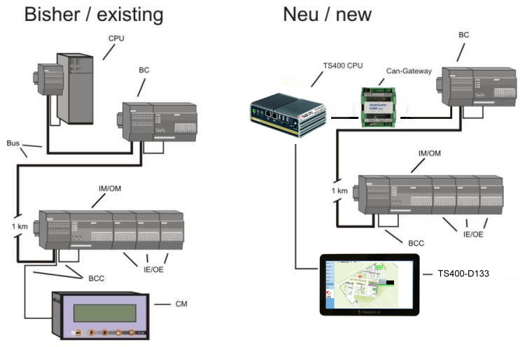
The TS200 modular annunciator system offers compliance to DIN 19235 with new value/first-up value indication. Alerts are signalized as text on the CM. As an option events can switch outputs, and a log printer can also be installed. The system is programmed using configuration software or an AT keypad. With its modular structure, separate components can be spaced apart up to 1000m along a thread-like Bus. The maximum upgrade capacity is 1280 I/O. The system can integrate up to 7 CM operating modules. The modular structure of the system makes use of nodes. A node always needs a BC bus connection module as well as an IM/OM input- or output module. Up to 7 IE/OE input- or output extensions can be added to each node. Two CPU processor module variants are available: -Small CPU with 256kB memory. Controls up to 4 nodes (256I/O) -Large CPU with 1MB memory. Controls up to 20 nodes (1280I/O) The system comprises the following primary components: TS200 CM Control Module
The CM represents the control and display unit of the system. All status- or fault messages are displayed in plain text. Fault messages are also indicated acoustically with the integrated horn. The CM has buttons for horn- and fault acknowledgement and also up and down arrows to move between the lines. You can also call up a log of the last 1,000 events on the CM. The CM has been designed for front panel mounting and is available in various language versions.  TS200 CPU Processor module
The CPU Processor module exchanges data and signals with the local modules. It monitors the operating status and power supply. It has an integrated lithium battery which safeguards data in the event of an interruption to the power supply. It also has a log memory for the last 1,000 events. The CPU is designed for mounting on a DIN rail, and is available in two versions: Small CPU 256kB up to 256 I/O, or Large CPU 1MB, 1,280 I/O  TS200 IM 24 Input module
The IM24 Input module is employed as the beginning of a node. It has 8 digital signal inputs for 24V DC. Three LEDs have been fitted on the front of the device to monitor communication and power supply. In addition, each input has an LED used to indicate its status. DIN rail assembly  TS200 IE 24/48/230 Input expansion module
The purpose of the IE 24/48/230 Input extension module is to increase the number of inputs. The 24V DC version has 8 digital signal inputs, the 48V DC and 230V AC versions have 4 digital signal inputs. Each input has an LED positioned on the front of the device to indicate its status. DIN rail mounting
TS200 OM 24 Output module
The OM 24 Output module is utilized as the beginning of a node. It has 8 digital 24V DC outputs. Three LEDs have been fitted on the front of the device to monitor communication and power supply. In addition, each output has an LED used to indicate its status. DIN rail mounting
TS200 OE 24/0.5, OE24/2.0 and OE 230 Output expansion modules
The purpose of the OE 24/0.5, OE24/2.0 and OE 230 Output expansion modules is to increase the number of outputs. The OE 24/0.5 and OE24/2.0 each have 8 digital outputs, which can handle loads of 0.5 or 2.0 Amps depending on the version. The OE 230/5.0 Output expansion module has 4 potential-free relay contacts (2 NO and 2 CO contacts). The status of each output is indicated with an LED on the front of the device. DIN rail mounting  TS200 BC Bus connection
The BC bus connection has two functions. First of all, it is used to supply the 24V DC operating voltage. Secondly, it is used as a junction between the bus and the cabling for the building. |

| Artikelnummer | Bild | Bezeichnung | Shop |
|---|---|---|---|
| 832.400.1 | ) |
Small CPU processor module 256kB |  |
| 832.400.10 | ) |
Large CPU processor module 1MB | |
| 832.400.2 | ) |
CM Control module | no longer available |
| 832.400.40 | ) |
IM24 Input module, 24V DC, 8 inputs | |
| 832.400.401 | ) |
IE24 extension module 24V DC 8 inputs | no longer available |
| 832.400.402 | ) |
IE48 Input extension module 12-48V DC, 4 inputs | |
| 832.400.403 | ) |
IE230 Input extension module 115-230V AC, 4 inputs | |
| 832.400.50 | ) |
OM24 Output module, 24V DC, 0.5A, 8 outputs | |
| 832.400.501 | ) |
OE 24/0.5 Output extension module, 24V DC, 0.5A, 8 outputs | |
| 832.400.502 | ) |
OE 24/2.0 Output extension module, 24V DC, 2.0A, 8 outputs | |
| 832.400.503 | ) |
OE 230/5.0 output extension module 230V AC, 5.0A, 4 relay outputs | no longer available |
| 832.400.801 | ) |
BC Bus connection module | |
| 832.400.802 | ) |
BCC 30 bus connection cable 0.3m | |
| 832.400.803 | ) |
BCC 300 bus connection cable 3.0m | |
| 832.900.001 | ) |
TS 10 screw-terminal block, 10 pole | |
| 832.900.015 | ) |
TC 2x 10 plug-in terminal block, 20 pole. | |
| 832.400.050 | ) |
AT compact keyboard | |
| 832.400.090 | ) |
PC terminal configuration programme for Windows | |
| 832.400.000 | ) |
System handbook DE/FRA/EN | |