 Description Description View View Technical data Technical data Downloads Downloads |
||
| TS200 CM control module | ||
Description
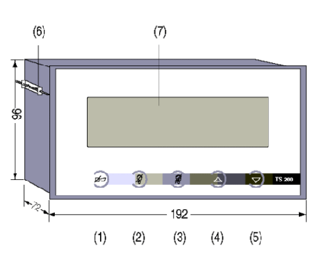
The CM control module is the man to machine interface in the TS-200 system. It has both a visual and acoustic output and is entry ready for operator use and configuration. Operators use the buttons on the front of the unit The system is configured using an AT keyboard.View
The graphic shows the front of the CM control module with its 4-row liquid crystal display and 5 user pushbuttons. These have pressure points which safeguard against being pressed accidentally. To assist users, the buttons next requiring activation in the alarm procedure are backlit. (1) Acoustic alarm acknowledgement (horn acknowledgement)
 (2) Single acknowledgement
(3) Double acknowledgement
(4) Go up a row
(5) Go down a row
(6) Assembly frame
(7) Liquid crystal display, 8 rows, each with 40 characters.
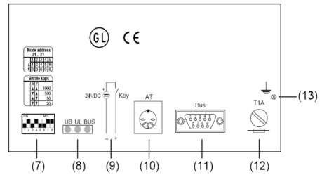
 The reverse side of the control module has the following
(7) A DIP switch used to adjust node numbers and bus transfer rate
(8) Three green LEDs for monitoring
(9) Connection for the key-operated switch
(10)Socket for the AT keyboard
(11)D-Sub-9 plug connector for the bus connection
(12)A fine-wire fuse (1 A, T type)
(13)Connection for HF earthing
Technical data
|
Display active surface size of display size of characters backlighting |
Liquid crystal display, dot matrix 127mm x 34mm 8 rows x 40 characters 5x7 dots LED, green |
| Acoustic alarm | Sound frequency 2,300Hz |
| User buttons Lighting |
Membrane keyboard with short-stroke keys LED, yellow |
| Keyboard requirement Connection Keyboard Layout Current consumption |
DIN plug connector, 5-pole 101/102 keys AT keyboard SG, GR, US, SF urrent consumption < 275 mA |
| Key-operated switch Input voltage: Released for operation Locked for operationt limit 1) nput current (at +24V DC) |
Passive, digital input 0 VDCNOM (< +5 VDC) +24 VDCNOM (> +14 VDC) -36 .. +36 VDC < 6 mA |
| Bus connection | CAN (ISO 11898) |
| Supply voltage UB operating range limit 1) max. power consumption |
24 VDCNOM +18 to + 36 VDC -36 to +36 VDC 10 W |
| Electric isolation Supply/logic, bus key Soperated input/logic, bus |
yes yes |
| Ambient temperature operating storage |
0 to +50 °C -20 to +60 °C |
| Protection category With front seal (optional) |
IP 20 IP 65 |
| Dimensions of front panel cutout |
B: 186 mm (+1.1, -0), H: 92 mm (+0.8, -0) |
| Dimensions |
192 x 72 x 96 mm |
| Weight | 900 g |
