 Description Description View View Schematic Schematic Technical data Technical data Downloads Downloads |
||
| TS200 OE output extensions | ||
Description
OE24/0.5 and OE24/2.0 output extensions modules offers eight digital outputs, OE230/5.0 offers four digital outputs. Up to 7 enhancement modules (IE and/or OE) can be connected to an output- or input module (OM or IM). The digital inputs are wired using a terminal block.View
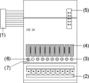
 (1) port to previous module
(2) socket for terminal blocks
(3) Orange LED lights when output active
(4) Labelling trips
(5) port for next module
(6) Red LED lights when short-circuit arises (OE 24/0.5 and OE 24/2.0 only)
(7) Green LED lights when supply voltage is present (OE 24/0.5 and OE 24/2.0 only)
Schematic
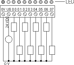
 The OE24 output enhancement modules offer eight digital outputs, each with a 24V DC output voltage. They are available in 0.5A and 2.0A variants.
Caution!
All the outputs have short-circuit protection. Nevertheless, the OE24/0.5 can be completely destroyed if overloaded!
All outputs have a common 0V connection (GND) and are galvanically isolated from the module logic.
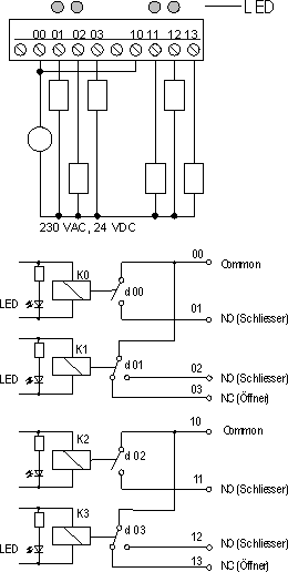
 The OE230/5.0 output enhancement modules offer four digital outputs, each having a voltage of 230V AC. It is equipped for a 5A switching current.
 Each pair of relay contacts have a common supply connection.
Technical data
| OE 24/0.5 |
OE 24/2.0 |
OE/230/5.0 |
Digital outputs output type switching voltage signal level without load signal = 0 signal = 1 output current T = 0 .. +35 ¦C T = +45 ¦C T = +55 ¦C short-circuit current typ. cut-off time restart time Total loading capacity Minimum switching current Limit. of inductive cut-off volt. Switching frequency max. Ohmic load Inductive load Consequence of overloading |
8 FET, positive switching less than +2 VDC +18 to +36 VDC less than 0.5 A less than 0.5 A less than 0.5 A 5 A 1.5 msec less than 5 sec 4 A 100 ÁA fly-wheel diode 100 Hz 2 Hz unit may be destroyed |
8 FET, positive switching less than +2 VDC +18 to +36 VDC less than 2.0 A less than 1.5 A less than 1.5 A 12 A 1.5 msec less than 5 sec 8 A 100 ÁA fly-wheel diode 100 Hz 2 Hz outputs deactivated |
4 Relays 2S/2U 5 ADC/AC 12 A 100 mA none with load max. 0.1Hz without load max. 20Hz |
| Power consumption, logic |
200 mW | 200 mW | 1 W |
| Electrical isolation Output / Logic Output / Output |
yes no |
yes yes |
yes yes |
| Ambient temperature Operating Storage |
0 to +55 ¦C -25 .. +70 ¦ |
0 to +55 ¦C -25 .. +70 ¦ |
0 to +55 ¦C -25 .. +70 ¦ |
| Protection category |
IP 40 | IP 40 | IP 40 |
| Dimensions (W x H x D) in mm | 55 x 58 x 85 | 55 x 58 x 85 | 55 x 58 x 85 |
| Weight |
140 g | 150 g | 150 g |
