
 |
 DescriptionTechnical dataSchematicOrder overviewDownloads DescriptionTechnical dataSchematicOrder overviewDownloads |
|
| Annunciator system LSX | ||
 Important information about the LSX
LSX Description
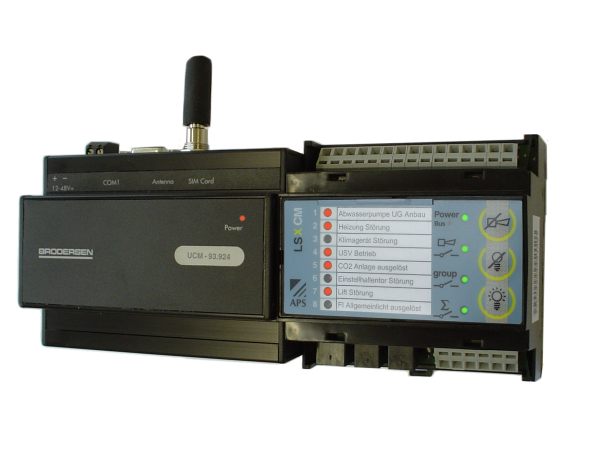
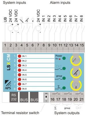
LSX, the modular annunciator system certified to DIN 19235 with new- or first-up value indication. Faults are indicated using the LED display on the CM and IM. An analogue- or GSM modem or a log printer can be connected to the CM. If a GSM modem is added to the system, status- or fault alerts can be sent via SMS/email or fax, or to a pager. For each LS CM or IM, up to 8 subscribers can be included in an alarm list. The parameters for the units are set via a terminal program. This is already available on all PCs: E.g. 'Hyperterminal' for Windows. The system is modular in design. Individual components can be removed if necessary. The maximum configuration is 256 1/0 with a maximum ring-shaped bus length of 1000m. The system comprises the following three primary components:LSX CM Communication Module
This module has three integrated buttons for horn- and lamp acknowledgement and lamp test. Each CM also comes with an integrated potential-free collective-, group- and horn output. The alarm LEDs can be labelled using insert strips. A modem (analogue- or GSM),a log printer or a Panelmodule PM can be connected to the CM.
LSX IM Input Module
Add-on module with an additional 8 inputs, identical to the CM, except does not have a communication interface. .
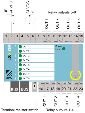
LSX OM Output Module
Output module with 8 freely-programmable relay outputs. The relay status is indicated via the LED on the front of the device. The module also has an integrated lamp test button. The alarm LEDs can be labelled using insert strips.
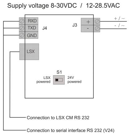
LSX Panel Modul PM
The panel module PM is used as remote display with 16 channels. It is directly connected to a communication module CM. The panel module PM shows automatically the information from the connected communication module and if installed, the communication- or input module with the next higher bus address.
Technical data
| Type | LSX CM Communication Module | LSX IM Input Module | LSX OM Output Module | LSX PM Panel Module |
|---|---|---|---|---|
| Image |  |
|
 |
|
| Part number | 832.650.020 | 832.650.010 | 832.650.030 | AS-D16-24-V24 |
| Housing plastic WxHxD | 87.5 x 90 x 58mm DIN | 87.5 x 90 x 58mm DIN | 87.5 x 90 x 58mm DIN | 72 x 144 x 74mm |
| Installation position | any | any | any | any |
| Connections | Cage clamp terminal blocks 2.5mm2 | Cage clamp terminal blocks 2.5mm2 | Cage clamp terminal blocks 2.5mm2 | Screw terminal max. 1.0mm2 |
| Temperature range | 0°C - +55°C | 0°C - +55°C | 0°C - +55°C | 0°C - +65°C |
| Protection category | IP20 | IP20 | IP20 | IP20 |
| Supply voltage | 24VDC +/-20% | 24VDC +/-20% | 24VDC +/-20% | 8-30VDC / 12-28.5VAC, 40-80Hz |
| Flashing frequency | 1Hz | 1Hz | 1Hz | 1Hz |
| Relay switching capacity | max. 3A / 250VAC | max. 3A / 250VAC | max. 3A / 250VAC | -- |
| Max. power consumption | 5W | 5W | 3W | 3W |
| Trip delay | approx. 10ms | approx. 10ms | approx. 10ms | approx. 10ms |
| Recovery time | approx. 1s | approx. 1s | approx. 1s | approx. 1s |
General info
Maximum bus length: 1000m (line) - required bus cable: U72 1x4x0.8 shielded
Schematic
Basic principle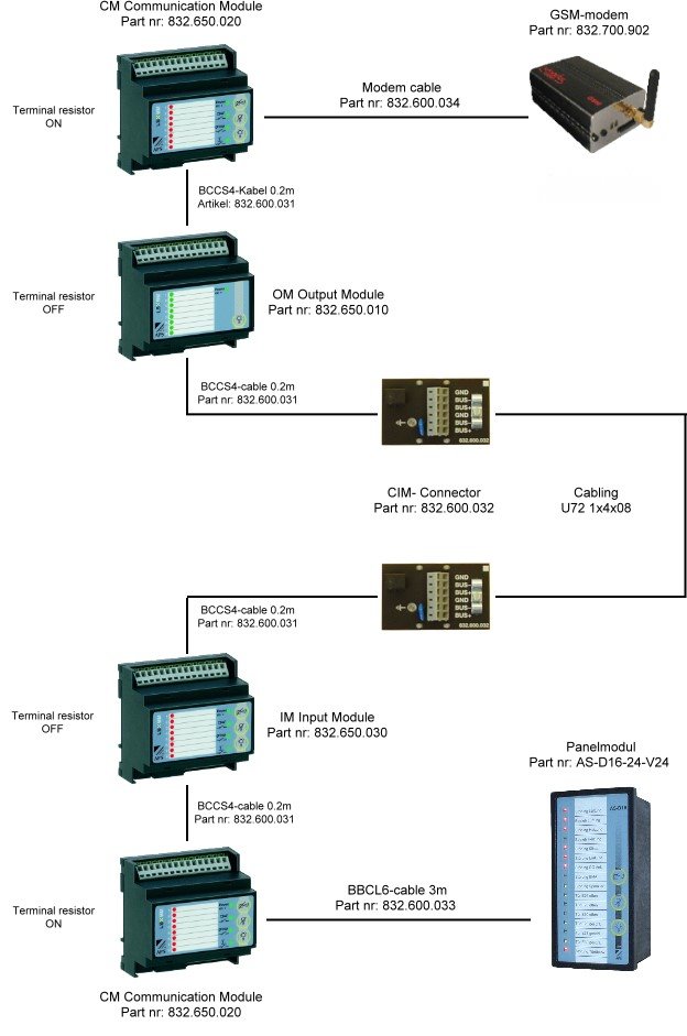
Connection diagram
LSX CM and IM communication modules
LSX OM output module
LSX PM panel module
Order overview
| Part number | Image | Description | Shop |
|---|---|---|---|
| 832.650.010 | ) |
LSX IM input module |  |
| 832.650.020 | ) |
LSX CM communication module | |
| 832.650.030 | ) |
LSX OM output module | |
| 832.600.035 | ) |
Programming cable | |
| 862.332.420 | ) |
EcoPower PSS 242 230V AC/24V DC 2A power supply unit for DIN rail mounting | |
| 832.600.031 | ) |
BCCS4 Bus cable, 0.2m for connecting modules | |
| 832.600.032 | ) |
CIM bus connection module (interface to building cabling) | |