
 |
 DescriptionProgrammingTechnical DataWiring DiagramView / Dimensional DrawingOrder OverviewDownloads DescriptionProgrammingTechnical DataWiring DiagramView / Dimensional DrawingOrder OverviewDownloads |
|
| Fault Indicator LSH08 | ||
LSH08 Description
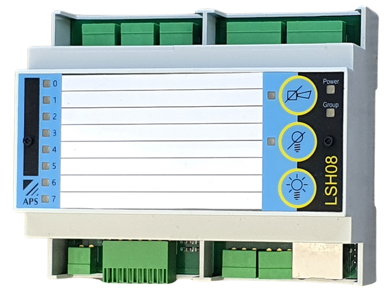
FunctionThe LSH08 is an 8-channel fault indicator for DIN rail mounting.
It offers integrated control elements for horn acknowledgement, message acknowledgement and lamp test.
The built-in buzzer can be deactivated if required. Each input can be individually switched between normally open (NO) and normally closed (NC).
A common delay can be activated for all fault inputs.
The signalling mode can be configured as new-value, first-up or common alarm.
Additional functions include automatic alarm acknowledgement after device start-up or collective outputs for priorities 1 and 2.
Labelling is done simply using an insert strip.
All settings, such as LED colour selection or input mode switching between NO/NC,
can be made either via the web interface (browser) or using the control buttons on the device front.
The device is connected via push-in terminals.
System Integration
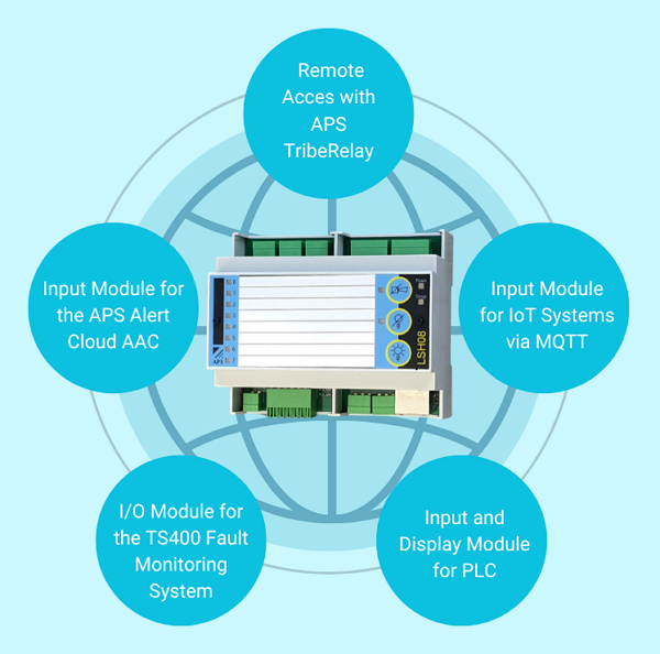
In addition to functioning as a local fault indicator, the LSH08 can be integrated into higher-level systems.
The connection is made via a network. Depending on the application, an outgoing internet connection may be required.
The LSH08 can be used as a universal input module for IoT systems and PLC controllers via MQTT or Modbus UDP.
The LSH08 also supports the APSdg protocol and can be used as an IO module for the APS Alert Cloud AAC and the APS TS400 alarm server.
Remote access and maintenance are ensured via APS-TribeRelay connection at no additional cost.
LSH08 Programming
Programming of the LSH08 fault indicator is carried out either via the web interface or using the control elements on the front of the device.View of the programming in the web interface:
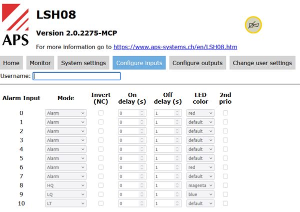
The use of the web interface is described in a separate document, see Downloads.
Parameter setting via the control elements on the front of the LSH08 takes place in four programming levels:
1. Inputs: Switching between NO and NC
2. Virtual DIP switch: Settings for delays, buzzer on/off, signalling mode, automatic alarm acknowledgement, and output modes
3. Assignment of inputs to collective output priority 2
4. RGB colour setting of fault inputs
Levels 3 and 4 are deactivated by default. They can be activated on level 2 via DIP switch 15.
Technical Data
| Designation | LSH08 Fault Indicator |
|---|---|
| Article Number | LSH08 |
| Signalling Mode | New-value, first-up or common alarm |
| Indication | 8 multicolour LEDs / integrated buzzer |
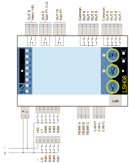
| Fault Inputs | 8 inputs, NO/NC configurable |
| System Inputs | 3 external lamp ack LQ, horn ack HQ and lamp test |
| Signal Outputs | 8 relay contacts in two groups |
| System Outputs | 3 horn output to HQ / collective output P1 / collective output P2 |
| Optional Output Functions | Button press HQ + LQ / collective prio 1+2 |
| Switching Capacity Output Relays | 6A 30VDC / 6A 250VAC |
| Delay Virtual DIP Switch | 5s/10s/60s uniform for all fault inputs |
| Delay in Web Interface | 1s to 48h individually per fault input |
| Automatic Alarm Acknowledgement | 5s/10s/60s uniform |
| NO/NC | All fault inputs individually switchable |
| Control Elements | Horn / Message acknowledgement / Lamp test |
| Operating Voltage | 8–30VDC / 12–28.5VAC, 40–80Hz |
| Signal Voltage | 24V AC/DC ±20% |
| System Input Voltage | According to operating voltage range |
| Protocols | APSdg / MQTT / Modbus-UDP |
| Power Consumption | Max. 4.5W |
| Weight | 210g |
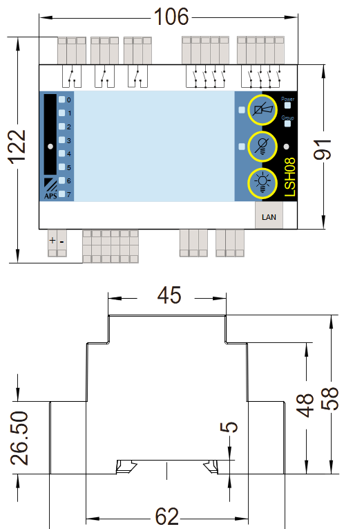
| Dimensions WxHxD without connector | 106x91x58mm |
| Dimensions WxHxD incl. connector | 106x122x58mm |
| Terminals | Push-in terminals 0.2–1.0mm² |
| Mounting Position | Any |
| Protection Class | IP20 |
| Mounting | 35mm DIN rail |
| Temperature Range | 0°C to +65°C |
Wiring Diagram
Dimensional Drawing
Order Overview
| Order number | Designation | Appendage | Stock*1 | Price*2 | ||
|---|---|---|---|---|---|---|
| LSH08 | Indicator unit 24V DC/AC | 2x 16 inputs, multicolour LED | 10 | 447.00 CHF |    |
| *1: Stock levels are for reference only. The handout is done upon incoming orders. |
| *2: Prices are uncommitted, errors are excepted. |