
 |
 DescriptionTechnical dataSchematicProgrammingOrder overveiwDownloads DescriptionTechnical dataSchematicProgrammingOrder overveiwDownloads |
|
| Annunciator system LSC | ||
 Important information about the LSC
LSC Description
LSC is the ideal fault monitoring system for the collective processing, display and acknowledgement of all alarms in a building or system. For example, activation of the lift alarm, a fault in the heating system, the failure of the garage door and the triggering of a CO2 alarm can be detected by one simple device which can also take the necessary action.The LSC fault monitoring system is a family of devices certified to DIN 19235 with new- or first-up value indication. Faults are indicated via an LED display and buzzer in the BM, and optionally in the PM. The devices can be programmed using the free software. The system is modular in design. The BM and RM modules can be positioned up to 1000m away from the CAN bus. The PM is integrated in the front panel of the cabinet or device and can be positioned up to 3m away from the associated BM. Both the BM and the RM are mounted on 35mm DIN rails. The system comprises the following three primary components:
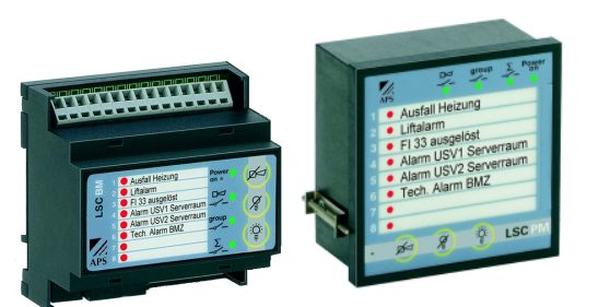
LSC BM Basic Module
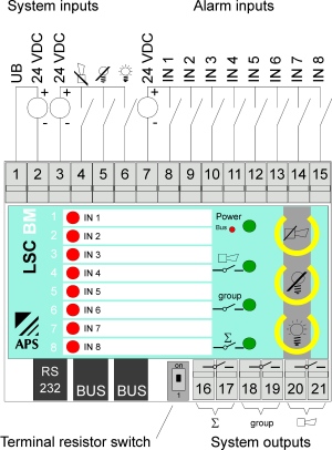
Master module with 8 inputs plus an LED display per input. This module has three integrated buttons for horn- and lamp acknowledgement and lamp test. Each BM also comes with an integrated potential-free collective-, group- and horn output. The alarm LEDs can be labelled using insert strips. Each input could be separately programmed if it is an NO or NC contact, Furthermore, each input can be delayed with a time from 1 to 255 seconds.
LSC RM Relay Module
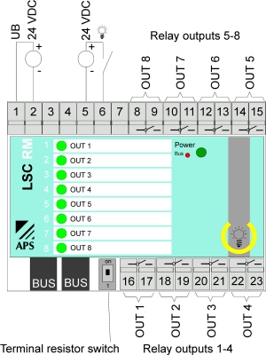
Relay module with 8 potential-free relays. The inputs on the BM can be connected to the RM. LEDs on the front panel indicates the status of the relay. These can be labelled using an insert strip. A button for the lamp test has been integrated into the front panel.
LSC PM Panel Module
The panel module serves as a separate control and display unit for front panel assembly. It indicates the fault alerts for the connected basic module. Buttons are also integrated for horn- and lamp acknowledgement and lamp test. The alarm LEDs can be labelled using insert strips.
Technical data
| Type | BM Basic Module | RM Relay Module | PM Panel Module |
|---|---|---|---|
| View |  |
 |
 |
| Part number | 832.600.012 | 832.600.022 | 832.600.000 |
| Housing | 87.5 x 90 x 58mm DIN | 87.5 x 90 x 58mm DIN | 96 x 96 x 51 mm Front panel assembly |
| Cutout | -- | -- | 92 x 92mm |
| Installaton position | any | any | any |
| Connections | Cage clamp terminal blocks 2.5mm2 | Cage clamp terminal blocks 2.5mm2 | -- |
| Temperature range | 0°C - +55°C | 0°C - +55°C | 0°C - +55°C |
| Degree of protection | IP20 | IP20 | IP40 |
| Supply voltage | 24VDC +/-20% | 24VDC +/-20% | 24VDC +/-20% |
| Flash frequency | 1 HZ | 1 HZ | 1 HZ |
| Relay switching capacity | max. 3A / 250VAC | max. 3A / 250VAC | -- |
| Max. power consumption | 5W | 3W | 2W |
| Trip delay | ca. 10ms | ca. 10ms | ca. 10ms |
| Recovery time | ca. 1s | ca. 1s | ca. 1s |
| Expansion capability | max. 8 BM | max. 8 RM | max. 8 PM |
| Bus length | 1000m | 1000m | 3m |
Schematic
Basic principle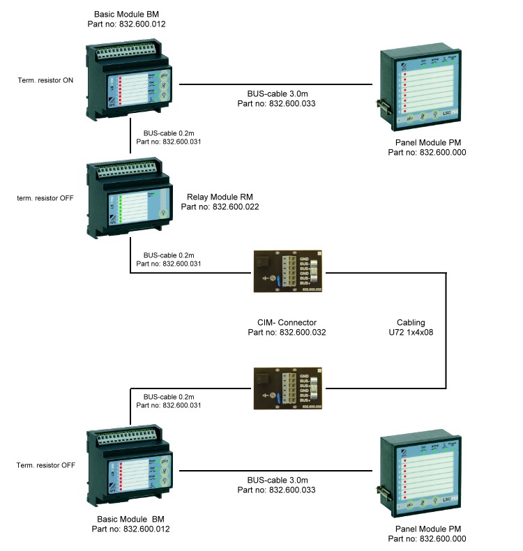
Connection diagram
LSC BM basic module
LSC RM relay module
Programming
The LSC is supplied as ready for operation in stand alone mode. To connect it to other modules, and to set up all parameters such as delay times, output configuration, etc., terminal software has also been provided. This software enables you to create, transfer and save all programmes with minimum fuss.View of the programming software: General configuration BM
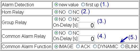
(1.) Alarm sequence new value up or first value up
(2.) Horn relay normally open (NO) or normally closed (NC)
(3.) Group relay normally open (NO) or normally closed (NC) and on delay in seconds
(4.) Common alarm relay normally open (NO) or normally closed (NC) and on delay in seconds
(5.) Common alarm relay function:
IMAGE (static)
The common alarm relay is activated by the first alarm and becomes inactive again when no further alarm conditions exist.
ACK (static until LQ)
The common alarm relay is activated by the first arriving alarm and becomes inactive again after the lamp acknowledgement. On the arrival of further alarms the collective alarm relay becomes active until the next lamp acknowledgement.
DYNAMIC
For each alarm arriving the common alarm relay becomes active in the cycle of the blinking frequency, until the lamp acknowledgement. On the arrival of further alarms the collective relay actively blinks again until the next lamp acknowledgement.
BLINK (dynamic/static)
The same functioning as for the common alarm DYNAMIC, but the relay remains statically active after the lamp acknowledgement until no further alarm conditions exist.
View of the programming software: Inputs BM
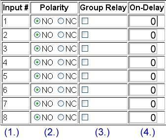
(1.) Inputs 1 to 8 of the BM
(2.) Input normally open (NO) or normally closed (NC)
(3.) Activation of the group relay of the BM
(4.) Input on delay in seconds
View of the programming software: Outputs RM
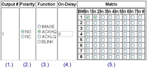
(1.) Outputs 1 to 8 of the RM
(2.) Output normally open (NO) or normally closed (NC)
(3.) Output function
IMAGE (static)
Image of the alarm linkage. The relay becomes statically active by the first alarm condition originating from the linkage. The relay output is reset when no more alarm conditions exist.
ACKHQ (static until HQ)
The relay is statically activated by the alarm linkage until the horn annunciator has been acknowledged.
ACKLQ (static until LQ)
The relay remains statically active due to the alarm linkage until the lamp acknowledgement has been activated.
BLINK (dynamic/static)
The relay remains set in blinking mode whilst alarm conditions are communicated via the linkage. After acknowledgement of the alarms the relay remains statically active until no more alarm conditions are communicated via the linkage.
(5.) Matrix to choose which input activates the output
Order overview
| Order number | Designation | Appendage | Stock*1 | Price*2 | ||
|---|---|---|---|---|---|---|
| 832.600.000 | LSC PM Panel module local, 24VDC |  | 396.00 CHF |    | ||
| 832.600.012 | LSC BM module base, 24VDC | with 8 inputs inclusive LED | 6 | 632.00 CHF | | |
| 832.600.022 | LSC RM module relay, 24VDC | with 8 outputs inclusive LED | 3 | 526.00 CHF | | |
| 832.600.030 | BCCS6 Bus cable 0.1m / 6-pole | 57 | 11.00 CHF | | ||
| 832.600.031 | BCCS4 cable bus 0.2m / 4-pole | 62 | 11.00 CHF | | ||
| 832.600.032 | CIM Bus connector-modul (LSC oder LSX) | 31 | 40.00 CHF | | ||
| 832.600.033 | BCCL6 cable bus 3.0m / 6-pole | 21 | 25.00 CHF | | ||
| 832.600.090 | LSC PC Termi-software incl. cable 3.0m | | 145.00 CHF | | ||
| 832.600.095 | LSC Programmierungskabel 3m | 1 | 48.00 CHF | | ||
| 832.600.903 | Marking labels LSC PM (3 pcs) | 919 | 9.00 CHF | |
| *1: Stock levels are for reference only. The handout is done upon incoming orders. |
| *2: Prices are uncommitted, errors are excepted. |