
 |
 DescriptionProgrammingTechnical dataSchematicDimensionsDownloads DescriptionProgrammingTechnical dataSchematicDimensionsDownloads |
|
| Operation-/Faultindicator AS-D16 | ||
 Important information about the AS-D16 operation-/faultindicator
AS-D16 Description
The AS-D16-BS is an operation/fault indicator with 16 channels for front assembly. It includes integrated controls for horn acknowledgment, alarm acknowledgment and lamp test. The built-in buzzer can be turned off. Each input (operation and fault input) can be switched separately between an opening contact and a closing contact. A time delay can be activated collectively for all fault inputs. The indicator process of the fault can be choosen between new value or first-up indication. The automatic alarm acknowledgment after energising the unit is activatable. It is also selectable if the operation LEDs shall be shown or suppressed during a fault condition. The AS-D16-BS has outputs both for the horn and collective output as well as for the lamp test. The function of the horn and collective output can be switched between the image of the control or remain active until acknowledgement. Programming is done using the controls built-in on the front. The AS-D16-BS is labelled with the supplied insert strips. The connection is done using the plug-in screw terminals on the back of the unit.AS-D16 Programming
The AS-D16-BS operation and fault indicator is programmed using the built-in controls. No other tool or software is required.AS-D16 has 3 programming levels:
1. Fault indicator inputs (red): Opening contact/closing contact switchover
2. Operating inputs (green): Opening contact/closing contact switchover
3. Virtual DIP switch: time delays, buzzer on/off, automatic acknowledgement and output modes
Technical data
| Type | Operation-/Faultindicator AS-D16 |
|---|---|
| Image | |
| Part number | AS-D16-24-BS |
| Communication | 16 LED Fault and Operation/Buzzer |
| Operation inputs | 16 inputs NO/NC each input separate |
| Fault inputs | 16 inputs NO/NC each input separate / Time delay global |
| Time delay fault inputs | 5s/10s/60s for all fault inputs, global |
| Automatic alarm acknowledgement after energising | 5s/10s/60s for all fault inputs, global |
| System imputs | External Horn acknowledgement / External Lamp acknowledgement / External Lamp test |
| System outputs | Horn acknowledgement / Lamp acknowledgement / Lamp test |
| Front control elements | Horn acknowledgement / Lamp acknowledgement / Lamp test |
| Supply voltage | 8-30VDC / 12-28.5VAC, 40-80Hz (using an AC supply disables the system outputs) |
| Signal voltage | 24V AC/DC ± 20% |
| Power consumption | Max. 3W |
| Weight | 260g |
| Dimensions WxHxD | 72x144x75mm |
| Front panel cut out | 138x68mm |
| Connectors | Plug-in screw terminals 0.2 - 2.5mm2 |
| Mounting position | Any |
| Protection degree housing | IP40 |
| Protection degree conntector | IP20 |
| Temperature range | 0°C to 65°C |
Schematic
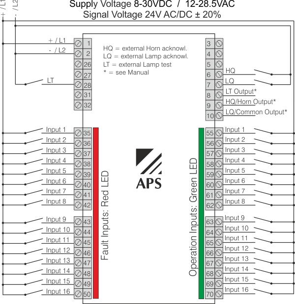
*The outputs LT (Lamp test), LQ (Lamp ack.) and HQ (Horn ack.) are only enabled using a DC power supply. The LQ and HQ functions can be customised, see the Programming chapter. The outputs are designed as a current sink and are not potential-free. If potential-free contacts are required, a relay must be utilised.
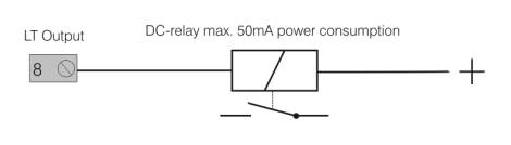
Wiring example for the LT output with an external relay:
Dimensions
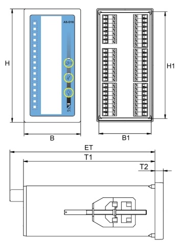
| H | B | H1 | B1 | ET | T1 | T2 |
|---|---|---|---|---|---|---|
| 144 mm | 72 mm | 136 mm | 65 mm | 75 mm | 52 mm | 8.5 mm |