| Type |
Operation-/Faultindicator AS-D16 |
| Image |
 |
| Part number |
AS-D16-24-BS |
| Communication |
16 LED Fault and Operation/Buzzer |
| Operation inputs |
16 inputs NO/NC each input separate |
| Fault inputs |
16 inputs NO/NC each input separate / Time delay global |
| Time delay fault inputs |
5s/10s/60s for all fault inputs, global |
| Automatic alarm acknowledgement after energising |
5s/10s/60s for all fault inputs, global |
| System imputs |
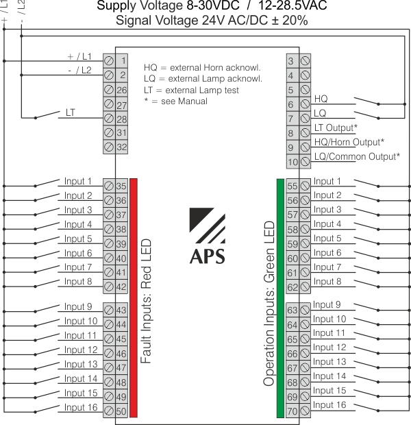
External Horn acknowledgement / External Lamp acknowledgement / External Lamp test |
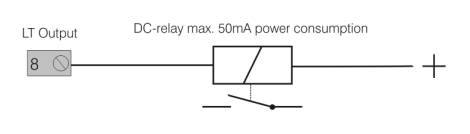
| System outputs |
Horn acknowledgement / Lamp acknowledgement / Lamp test |
| Front control elements |
Horn acknowledgement / Lamp acknowledgement / Lamp test |
| Supply voltage |
8-30VDC / 12-28.5VAC, 40-80Hz (using an AC supply disables the system outputs) |
| Signal voltage |
24V AC/DC ± 20% |
| Power consumption |
Max. 3W |
| Weight |
260g |
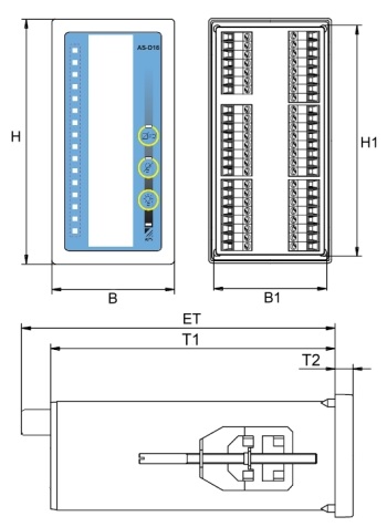
| Dimensions WxHxD |
72x144x75mm |
| Front panel cut out |
138x68mm |
| Connectors |
Plug-in screw terminals 0.2 - 2.5mm2 |
| Mounting position |
Any |
| Protection degree housing |
IP40 |
| Protection degree conntector |
IP20 |
| Temperature range |
0°C to 65°C |
 Description
 Important information about the AS-D16 operation-/faultindicator