
 |
 DescriptionIntegrationSchematicDimensionsTechnical dataDownloads DescriptionIntegrationSchematicDimensionsTechnical dataDownloads |
|
| TS400 Autonomous input modules | ||
Description
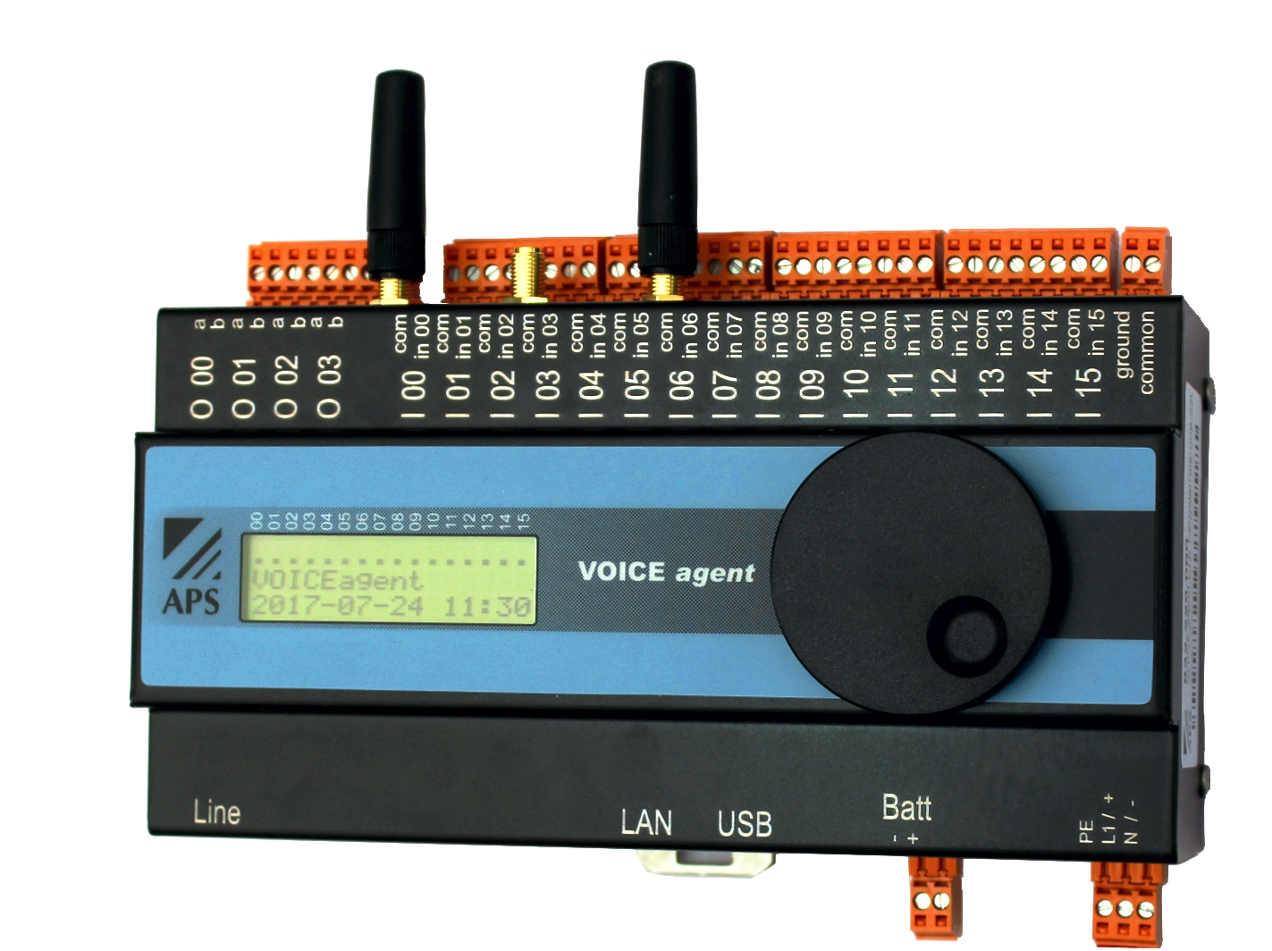
The signals from outdoor stations or other buildings are integrated in the TS400 monitoring and management system with the help of the TS400 Autonomous input modules. The advantage compared to the local I/O is that the autonomous input modules are also completely functional independently. The autonomous input modules are complete alarm systems that report their status to the supervisory TS400. Apart from the 16 inputs, the autonomous input modules also have a display, a modem, a mains adapter and a rechargeable battery controller integrated in them.The autonomous input modules are configured separately with the help of the browser, and the time delay in the alarm group is selected in such a manner that the TS400 handles the primary alarm generation function. If the autonomous input module does not receive any acknowledgement from the TS400 within the period of time delay, the secondary alarm is triggered directly on the autonomous input module. The options available for the secondary alarm route include the dispatch of voice messages, e-mail or SMS. Depending on the application, the autonomous input modules are available with a GSM modem or analogue modem and a power supply unit of 110-230 V AC or 24 V DC. Each autonomous input module has 16 inputs, up to 8 of which can be reconfigured as analogue input modules. For the analogue inputs, three switching thresholds are formed and transmitted to the TS400
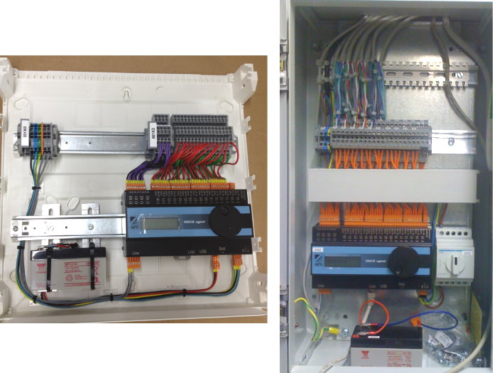
Application examples:
Integration
The TS400 Autonomous input modules are linked to the TS400 CPU Processor module via the network. With the default settings, the autonomous input modules transmit the data in broadcast mode. If automatic detection and integration of the APSdg modules is enabled on the TS400 CPU Processor module, and if the TS400 autonomous module is accessible in the same network, the signals are linked automatically. In case of a link via an external network / Internet, the TS400 CPU Processor module requires a fixed IP address..View in the TS400

View of the node in the TS400
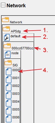
1. Folder for the APSdg modules to which the autonomous modules belong
2. Default settings and standard response of all APSdg modules
3. Address of the APSdg module detected
4. SIG of the APSdg module
The other configuration is identical to that for the SIG of the standard I/Os.
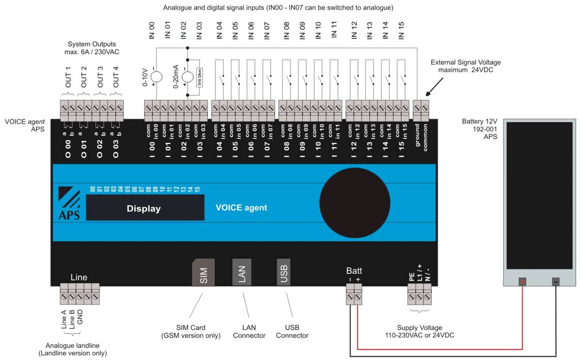
Schematic
Basic connection principle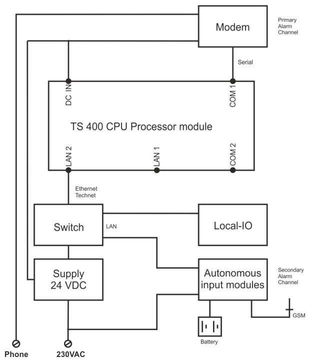
Schematic of the module
Please click on the image for a larger view or go to the download of the wiring diagram sheet
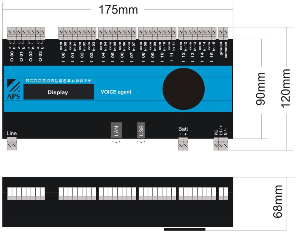
Dimensions
Please click on the image for a larger view
Technical data
| Inputs | Total 16, up to 8 analogue |
|---|---|
| Digital inputs | 24VDC NO or NC |
| Analogue inputs | 0-10V or 0-20mA with shunt |
| Outputs | 4 potential free relays |
| Switching capacity, outputs | Max. 6A / 230VAC AC1 |
| Supply voltage AC version | 230VAC (100-240VAC / 47-63Hz) |
| Supply voltage DC version | 24VDC (18-70VDC) |
| Power consumption | Max. 10W |
| Internal signal voltage | 15VDC internally generated |
| External signal voltage | 24VDC max. |
| Modem landline version | Analogue a/b |
| Modem GSM version | GSM 900/1800MHz / SMA connector |
| Network LAN | Static IP-Address or DHCP |
| Battery charger | Integrated for 12V accumulator up to 3Ah |
| Display | 3 Row-LCD-display backlit |
| Number of speech files | 32 |
| Number of phone numbers | 30 |
| Number of alarm profiles | 8 |
| Time channels | 8 |
| Speech files formats | Usual sound files like wav, raw, pcm, mp3 |
| Housing | Metal powder coated |
| Dimensions WxHxD (without connectors/knob) | 175 x 90 x 59 mm |
| Dimensions WxHxD (with connectors/knob) | 175 x 120 x 68mm |
| Weight | Appr. 650g |
| Mounting position | Any |
| Mounting | 35mm DIN-Rail or 19" Rack with optional rack panel: PS-3U |
| Connectors | Screw-plugterminals max. 1,5mm2 |
| Ambient temperature | 0°C bis +40°C |
| Protection degree | IP20 |
| Real time clock | Automatic leap-year adjustment. Accurate to less than +/- 1s at 25°C |