
 |
 DescriptionFunction diagramSchematicProgrammingTechnical dataOrder overviewDownloads DescriptionFunction diagramSchematicProgrammingTechnical dataOrder overviewDownloads |
|
| Common alarm indicator LSA | ||
 Important information about the LSA
Description
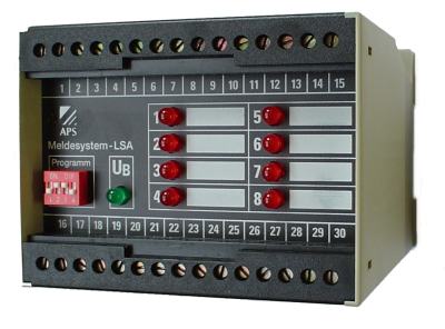
GeneralThe LSA annunciator system is made up of two function modules. These can be either used alone or in combination, depending on the particulars of the application.
1. Master module with single indication
The master module contains the horn output (relay contact) and group alarm (relay contact) functions required for a complete alarm system. There are also 8 signal inputs which control a group alarm relay. Each fault alert received by the master module inputs is indicated as a continuous light on the integrated LED. 8 lamp outputs are available for the use of additional, external indicator lamps.
2. Group module with individual indication
The group module is configured for 8 signal inputs which work on a group relay. The group module can be used for basic alarm requirements without a master module, when only the group alarm (relay) and the single- group display are required. Each incoming fault alert is indicated by an LED assigned to the respective input. 8 lamp outputs are available for the use of additional, external indicator lamps.
3. Loss of voltage
Active alerts will be retained even if the operating voltage is disconnected.
Function
Each incoming fault alert is indicated via a continuously lit LED.br>
1. Common alarm (master module only)
The relay for common alarm remains energized as long as any group alarm is present. Once a group alarm is no longer present, the relay will return to its normal state.
2. Group alarm
The relay for group alarm remains energized for as long as a fault alert for the assigned group is present. Once the last fault has been fixed, the relay will return to its normal position.
3. Horn
The horn relay is energized by the first incoming fault alert. The horn relay can be reset at the Input HQ. The horn relay energizes again if any other fault alerts arrive. The horn relay will remain energized until it is acknowledged, even if the fault alert is no longer present.
4. Lamp test
All the modules come with a special lamp test switch. If a signal intrudes at the lamp test input, a relay in the module will take up the lamp test. This relay is used to relieve the button for the lamp test as the auxiliary relay takes up all the lamp current. A specially developed switch can also be used to enable a lamp test in AC operation. When using AC, the lamp check works with pure alternating current and not with half-waves, which is the generally accepted method. There is no loss of brightness.
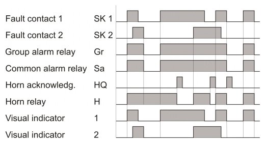
Function diagram
The group relay remains energized for as long as any alert of the corresponding group module is still active. Once the fault contact becomes active, the visual indicators will immediately show a continuous light. They are active in parallel with the fault contacts.
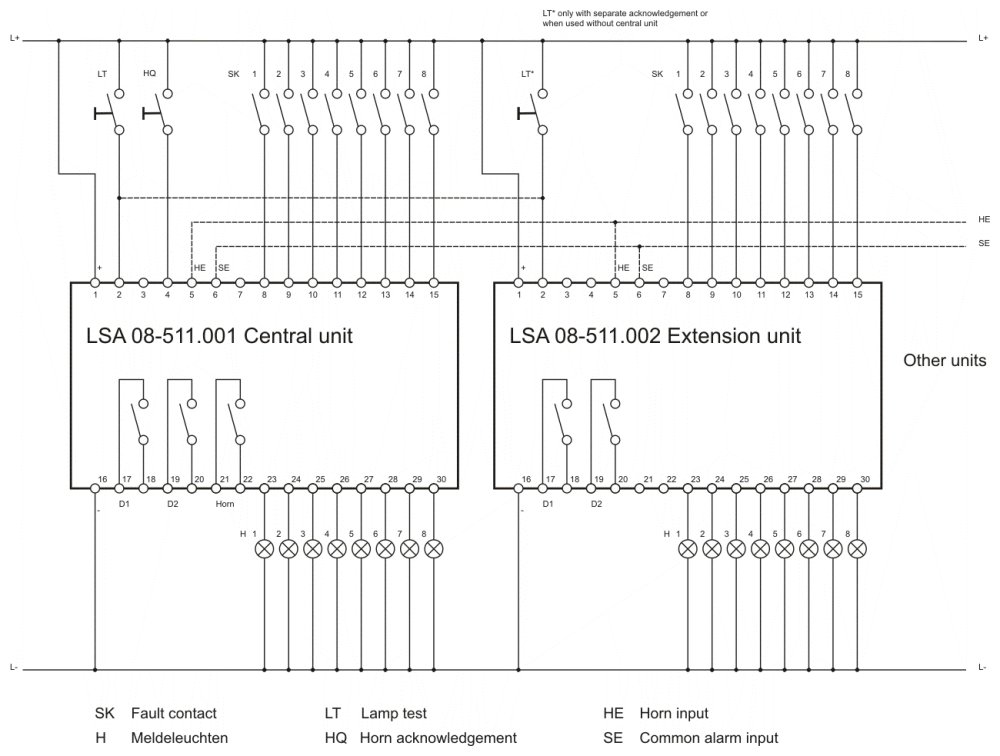
Schematic
Please click on the image for a larger view or download the diagram sheet
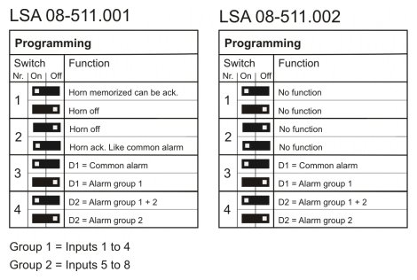
Programming
The LSA is programmed by a DIP-switch as followed:
Technical data
| Signal inputs | 8 |
|---|---|
| Operating voltage | 20-30VDC |
| Max. permissible ripple | max. 15% |
| Power consumption | max. 1W |
| Temperature range | -20 - +70°C |
| Installation position | any |
| Switching capacity (relay contacts) | 250VAC 5A |
| Protection category Housing | IP40 |
| Protection category Terminals | IP20 |
| Connections | 4mm² (2x1.5mm²) |
| Weight | 300g |
| Dimensions WxHxD | 99.7x75x110mm |
Order overview
| Order number | Designation | Appendage | Stock*1 | Price*2 | ||
|---|---|---|---|---|---|---|
| LSA08-511.001 | LSA08 common alarm | cental unit, B=24VDC / M=24VDC | 3 | 688.00 CHF |    | |
| LSA08-511.002 | LSA08 common alarm | group module, B=24VDC / M=24VDC | 4 | 682.00 CHF | |
| *1: Stock levels are for reference only. The handout is done upon incoming orders. |
| *2: Prices are uncommitted, errors are excepted. |