 Description
 View
View Schematic
 Technical data
 Downloads
 Description Description View View Schematic Schematic Technical data Technical data Downloads Downloads |
||
| TS200 IM 24 input module | ||
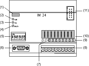
 (1) labelling strip (node number)
| Digital inputs (IEC1131-2) Input voltage: Signal = 0 Signal = 1 Limits Input current (at +24 VDC) Input resistor Connecting cable for sensor Shielding |
8 0 VDC NOM (< +5 VDC) +24 VDC NOM (> +14 VDC) -36 .. +36 VDC 6 mA typ. 3.9 kOhm max. 100 m not required |
| Bus connection |
CAN (ISO 11898) |
| UB power supply Operation range Limits Power consumption: Without IE / OE Full configuration |
+24 VDC NOM +18 .. +36 VDC -36 .. +36 VDC max. 2.1 W max. 9 W |
| Electrical isolation Supply / Logic and bus Inputs / Logic and bus Inputs / Inputs |
yes yes no |
| Ambient temperature Operating Storage |
0 to +55 °C -25 to +70 ° |
| Protection category |
IP 40 |
| Dimensions (W x H x D) in mm | 100 x 58 x 85 |
| Weight
|
220 g |