The LSE New value/First-up indicator is designed to signalise technical faults according to the DIN 19235 sequence. You may choose between New Value or First-up indication.
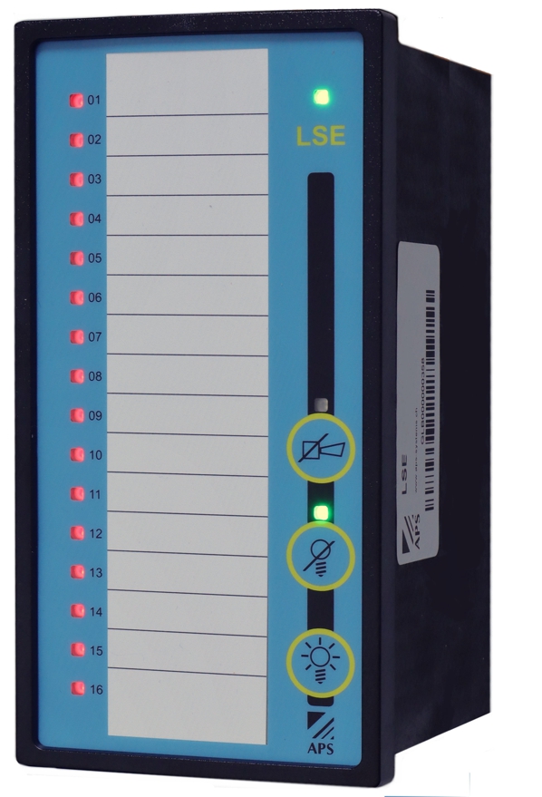
The LSE front panel contains 16 LEDs for alarm messages and 1 green LED for system operation indication. The standard colour of the LED for the alarm messages is red, other colour variants are available.
To build larger systems with a higher amount of inputs than a single device offers, it is possible to connect up to twelve units.
The devices are equipped on the front side with one button each for lamp test (LT), lamp acknowledgement (LQ) and horn acknowledgement (HQ). A buzzer is integrated in the unit.
The operation can also be carried out by external buttons. The signal inputs can be switched in two groups of eight between normally closed and normally open.
A on delay of 5, 60 or 600 seconds can be set globally for all signal inputs. A potential-free contact (1 NO contact) is available for an external audible alarm (horn).
The relays for collective and group alarm each have one contact with common potential. Normally closed or normally open can be selected for both relays.
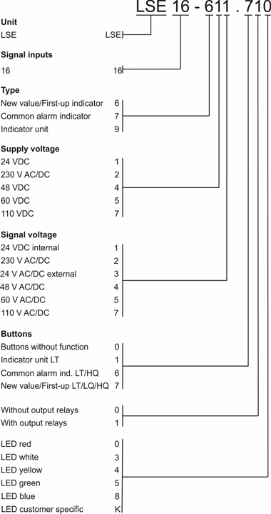
The signal and supply voltage is available in various common variants. As a further option, devices with one output relay per input are available.
Function
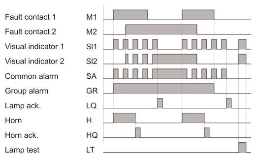
First-up indication
If several alarms occur one after the other or almost simultaneously, only the message that occurred first is indicated by a flashing light.
If the alarm is inactive before lamp acknowledgement, the visual indicator flashes until lamp acknowledgement, after which it goes out.
If a further alarm appears after horn acknowledgement but before lamp acknowledgement, the horn will not become active again. All further alarms are displayed in continuous light as long as they are present.
At the same time the relay output is activated for an acoustic signal (terminals 3 and 4).
When the lamp acknowledgement is activated, the visual indicator of the first stored message changes to continuous light, provided the fault still exists.
If the fault has been eliminated in the meantime, the visual indicator goes out. The audible alarm (horn) must always be acknowledged first.
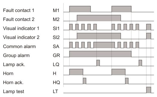
New value indication
Each incoming alarm is indicated by the corresponding visual indicator flashing. At the same time the relay output is activated for an audible alarm (connectors 3 and 4).
When the lamp acknowledgement button is pressed, the visual indicator changes from flashing to continuous light, when the alarm still persists.
If a further alarm occurs after the horn has been acknowledged but before lamp acknowledgement, the horn remains inactive and the visual indicator flashes until lamp acknowledgement.
If the alarm has meanwhile disappeared, the visual indicator goes out. The audible alarm (horn) must always be acknowledged first.
Signal inputs M
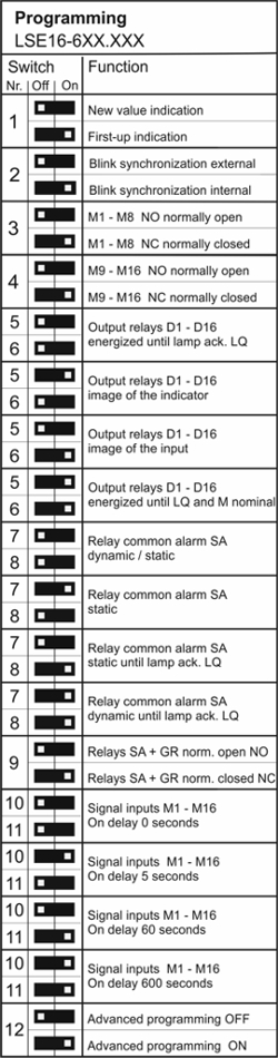
The signal inputs can be reprogrammed with the DIP switches 3 and 4 in two groups of eight to either normally open NO or normally closed NC.
With the DIP switches 10 and 11 a globally input delay of 0, 5, 60 or 600 se-conds can be selected.
Output relays D (optional)
The output relays are connected to the signal input carrying the same number. The function can be programmed with the DIP switches 5 and 6 as followed:
DIP Switch 5 off / DIP Switch 6 off
Relays remain activated until lamp acknowledgement LQ.
DIP Switch 5 on / DIP Switch 6 off
Relays as an image of the visual indicator (change blinking, static).
DIP Switch 5 off / DIP Switch 6 on
Relays as an image of the signal input.
DIP Switch 5 on / DIP Switch 6 on
The relays remain latched until lamp acknowledgement LQ and the signal input M is back in its nominal state.
Audible device / Horn
The internal buzzer and the horn relay are activated by the signal inputs.
The relay stays active until acknowledgement even when the signal inputs went off meanwhile. Acknowledgement is possible with the HQ button or an external switch.
Lamp test LT
The lamp test button or lamp test input activates all LED's for about 5 seconds.
If several units are connected together the lamp test is overlapping. If the output relays are programmed as image of the LED they are also activated.
Group alarm relay GR
The relay for group alarm is switched on as long as any message from the associated device is present. If there is no more alarm pending, the relay drops back.
The DIP switch 9 can be used to switch between normally closed and normally open for the two relays common and group alarm..
Common alarm relay SA
The function of the common alarm relay can be programmed with the DIP Switches 7 and 8 as followed:
DIP Switch 7 off / DIP Switch 8 off
Dynamic static, with each incoming alarm the common alarm relay is acti-vated in step with the flashing frequency until lamp acknowledgement.
After acknowledging the alarm, the indicator changes to continuous light until the alarm disappears. With each new alarm the relay is activated until lamp acknowledgement.
DIP Switch 7 on / DIP Switch 8 off
Static, the common alarm relay is activated by the first alarm to arrive and stays active until the last alarm disappeared.
DIP Switch 7 off / DIP Switch 8 on
Static until LQ, the common alarm relay is activated by the first alarm to arrive and stays active until lamp acknowledgement.
With each new alarm the relay is activated until lamp acknowledgement.
DIP Switch 7 on / DIP Switch 8 on
Dynamic until LQ, with each incoming alarm the common alarm relay is activated in step with the flashing frequency until lamp acknowledgement.
With each new alarm the relay is activated until lamp acknowledgement.
The DIP switch 9 can be used to switch between normally closed and normally open for the two relays common and group alarm.
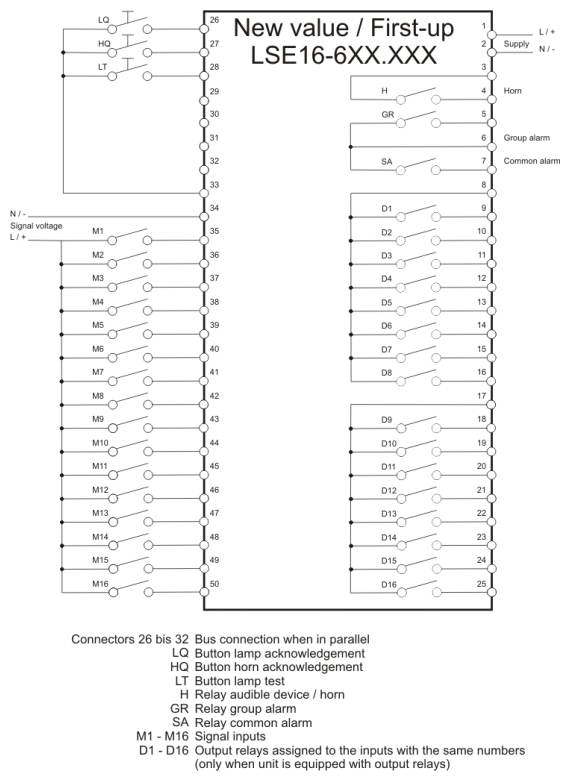
New value/First-up indicator with external signal voltage
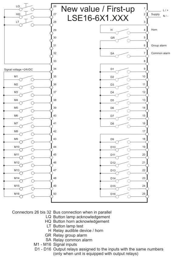
New value/First-up indicator with internal signal voltage
Parallel connection
To build larger systems, it is possible to connect up to twelve units. The alarm acknowledgement, the horn acknowledgement, the lamp test, the common alarm relay and the horn are activated overlapping. The connectors are used as follows:
Connector 26: Alarm acknowledgement (external and overlapping)
Connector 27: Horn acknowledgement (external and overlapping)
Connector 28: Lamp test (external and overlapping)
Connector 29: Synchronisation of the blinking frequency (DIP-switch 2 must be set "on" on one unit, all others "off")
Connector 30: First value signalisation (only when using "first-up" sequence)
Connector 31: Common alarm relay activation
Connector 32: Horn activation
Connector 33: Ground
Programming
The programming of the LSE new value / first-up indicator is effected by a DIP-switch as followed:
M: Signal inputs
D: Optional output relays
HQ: Horn acknowledgement
SA: Common alarm relay
GR: Group alarm relay
NO: Normally open
NC: Normally closed
 Description