 DescriptionFunction diagramSchematicProgrammingDimensionsTechnical dataOrder overviewDownloadsLink to predecessor model
 |
DescriptionFunction diagramSchematicProgrammingDimensionsTechnical dataOrder overviewDownloadsLink to predecessor model |
|
| LSE Indicator unit | ||

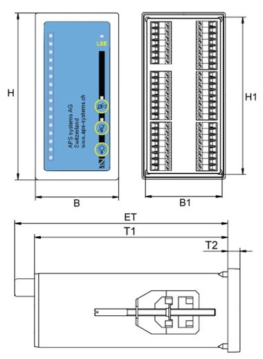
| H | B | H1 | B1 | ET | T1 | T2 |
|---|---|---|---|---|---|---|
| 144mm | 72mm | 136mm | 65mm | 170mm | 154mm | 8.5mm |
| General | |
|---|---|
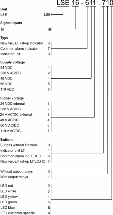
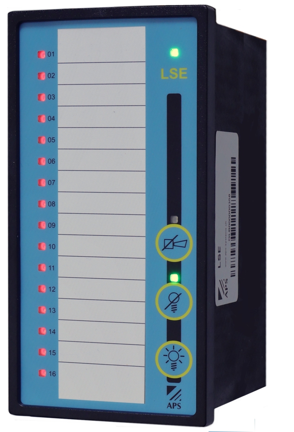
| Signalisation | 16 LED |
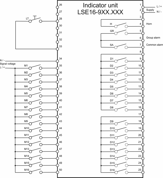
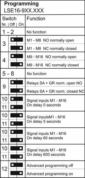
| Signal inputs | NO or NC selectable in two groups |
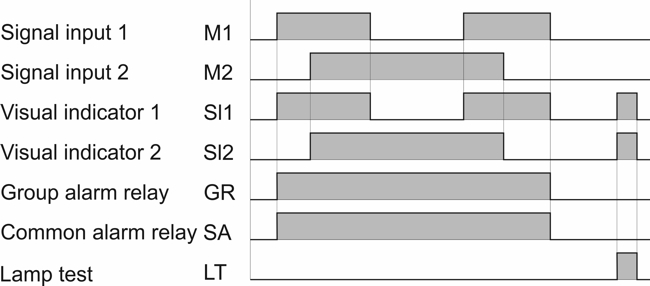
| On delay signal inputs M | 0 / 5 / 60 / 600 seconds |
| Reaction time signal inputs M | 1 second |
| LED colours | Red, white, yellow, green, blue |
| Power consumption idle | 3W |
| Power consumption maximum | 20W |
| System relays H/GR/SA | Switching capacity 250VAC 6A |
| Output relays D | Switching capacity 250VAC 6A |
| Frequency range AC versions | 40-60 Hz |
| Weight without output relays D | 580g |
| Weight with output relays D | 680g |
| Dimensions WxHxD | 72x144x170mm |
| Front cut-out | 138x68mm |
| Connectors | Plug-in screw terminals 0.2 – 2.5mm2 |
| Mounting position | Any |
| Protection degree housing | IP40 |
| Protection degree connectors | IP20 |
| Temperature range | -20 to +65°C |
| Signal voltages | |
| External versions | 24 / 48 / 60 / 110 / 230V AC/DC |
| Internal version | 24VDC |
| Threshold ON | 2/3 of the signal voltage (peak) |
| Threshold OFF | 1/2 of the threshold ON |
| Voltage endurance | 360VAC / 500VDC |
| Supply voltages | |
| 24VDC | 20-30 VDC |
| 48VDC | 40-55 VDC |
| 60VDC | 51-78 VDC |
| 110VDC | 93-127 VDC |
| 230V AC/DC | 90-260 VAC / 126-360VDC |
| Artikelnummer | Bezeichnung | Zusatz | Bestand*1 | Preis*2 | ||
|---|---|---|---|---|---|---|
| LSE16-911.100 | LSE16 Anzeigebaustein LED rot | Taste: LT, B: 24VDC, M: 24VDC, ohne Relais |  | 484.00 CHF |    | |
| LSE16-911.104 | LSE16 Anzeigebaustein LED gelb | Taste: LT, B: 24VDC, M: 24VDC, ohne Relais | | 484.00 CHF | | |
| LSE16-911.105 | LSE16 Anzeigebaustein LED grün | Taste: LT, B: 24VDC, M: 24VDC, ohne Relais | | 484.00 CHF | | |
| LSE16-911.110 | LSE16 Anzeigebaustein LED rot | Taste: LT, B: 24VDC, M: 24VDC, mit Relais | | 543.00 CHF | | |
| LSE16-911.114 | LSE16 Anzeigebaustein LED gelb | Taste: LT, B: 24VDC, M: 24VDC, mit Relais | | 543.00 CHF | | |
| LSE16-911.115 | LSE16 Anzeigebaustein LED grün | Taste: LT, B: 24VDC, M: 24VDC, mit Relais | | 543.00 CHF | | |
| LSE16-922.100 | LSE16 Anzeigebaustein LED rot | Taste: LT, B: 230VACDC, M: 230VACDC, ohne Relais | | 629.00 CHF | | |
| LSE16-922.104 | LSE16 Anzeigebaustein LED gelb | Taste: LT, B: 230VACDC, M: 230VACDC, ohne Relais | | 629.00 CHF | | |
| LSE16-922.105 | LSE16 Anzeigebaustein LED grün | Taste: LT, B: 230VACDC, M: 230VACDC, ohne Relais | | 629.00 CHF | | |
| LSE16-922.110 | LSE16 Anzeigebaustein LED rot | Taste: LT, B: 230VACDC, M: 230VACDC, mit Relais | | 696.00 CHF | | |
| LSE16-922.114 | LSE16 Anzeigebaustein LED gelb | Taste: LT, B: 230VACDC, M: 230VACDC, mit Relais | | 696.00 CHF | | |
| LSE16-922.115 | LSE16 Anzeigebaustein LED grün | Taste: LT, B: 230VACDC, M: 230VACDC, mit Relais | | 696.00 CHF | |
| *1: Lagerbestände sind Richtwerte. Die Zuteilung erfolgt nach Bestelleingang. |
| *2: Preise sind nicht verbindlich, Irrtum ist vorbehalten. |