 DescriptionFunctionTechnical dataSchematicOrder overviewDownloads
 |
DescriptionFunctionTechnical dataSchematicOrder overviewDownloads |
|
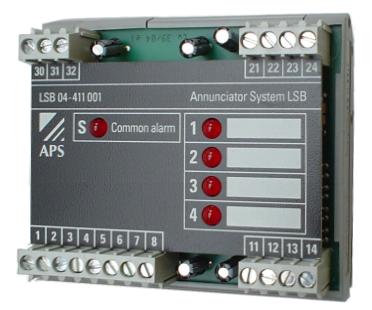
| Common alarm indicator LSB | ||
| 24V AC/DC version | 230V AC version | |
|---|---|---|
| Number of alerts | Master module 4/ Extension module 8 | Master module 4/ Extension module 8 |
| Supply- and alarm voltage | 24VAC/DC +-15% | 230VAC +-15% |
| Power consumption | max. 2W | max. 5W |
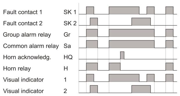
| Response time | approx. 100ms | approx. 100ms |
| Recovery time | approx. 500ms | approx. 500ms |
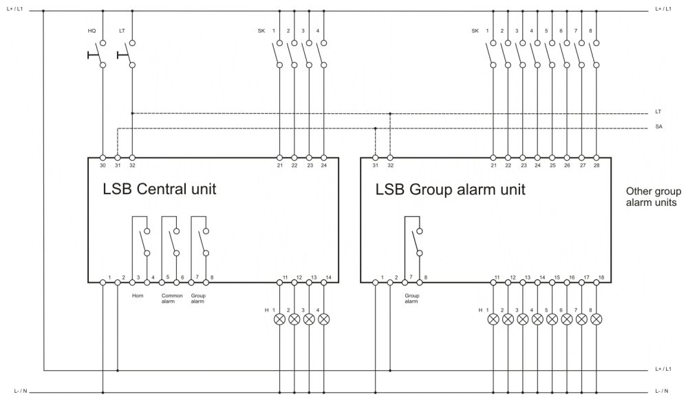
| Switching capacity (relay contacts) | 4A 230V | 4A 230V |
| Connections | max. 4mm2 or 2x1,5mm2 | max. 4mm2 or 2x1,5mm2 |
| Installation position | any | any |
| Weight | approx. 150g | approx. 150g |
| Dimensions | 77x90x45mm | 77x90x45mm |
| Artikelnummer | Bezeichnung | Zusatz | Bestand*1 | Preis*2 | ||
|---|---|---|---|---|---|---|
| LSB04-411.001 | LSB04 Sammelmelder 24V AC/DC | Zentralbaustein mit 4 Eingänge | 1 | 347.00 CHF |    | |
| LSB04-422.001 | LSB04 Sammelmelder 230VAC | Zentralbaustein mit 4 Eingänge | 7 | 433.00 CHF | | |
| LSB08-411.002 | LSB08 Sammelmelder 24V AC/DC | Gruppenbaustein mit 8 Eingänge |  | 271.00 CHF | | |
| LSB08-422.002 | LSB08 Sammelmelder 230VAC | Gruppenbaustein mit 8 Eingänge | 2 | 340.00 CHF | |
| *1: Lagerbestände sind Richtwerte. Die Zuteilung erfolgt nach Bestelleingang. |
| *2: Preise sind nicht verbindlich, Irrtum ist vorbehalten. |