
 |
 DescriptionTechnical dataSchematicDimensionsDownloadsLink to the successor model LSE-D16 DescriptionTechnical dataSchematicDimensionsDownloadsLink to the successor model LSE-D16 |
|
| AS-D16 Indicator unit | ||
 Important information about the AS-D16 indicator unit
AS-D16 Description
The indicator unit AS-D16 is equipped with 16 DUO-LED's designed for front panel assembly. Besides the LED's the units has an integrated buzzer which can be activated by an seperate input. A button for the lamp test has been implemented into the front panel as well as additional control elements which allows the integration in a higher-ranked system. The LED's can be labelled using a insert strips. All electrical connections are realised by plug-in screw terminals on the back of the unit.Technical data
| Communication | 16 DUO LED's / integrated buzzer |
|---|---|
| Indicator inputs | 16 inputs for each colour |
| System inputs | Buzzer / Lamp test / Common alarm |
| System outputs | Buzzer ack. / Alarm ack. / Lamp test |
| Control elements | Buzzer ack. / Alarm ack. / Lamp test |
| Supply voltage | 8-30VDC / 12-28.5VAC, 40-80Hz (When using AC input votlage the system outputs are disabled) |
| Signal voltage | 24V AC/DC ± 20% |
| Power consumption | Max. 3W |
| Temperature range | -0°C to 65°C |
| Weight | 260g |
| Dimensions | WxHxD 72x144x61mm (without terminals) |
| Front panel cut out | 138x68mm |
| Terminals | Plug-on screw terminals, max 2,5mm2 |
| Mounting position | Any |
| Protection degree | IP20 |
Schematic
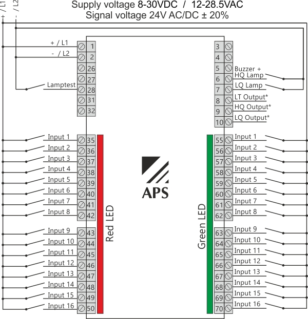
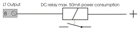
*The outputs LT (Lamp test), LQ (Lamp ack.) und HQ (Horn ack.) are only enabled using a DC power supply. They were activated by pressing the buttons on the front of the unit. These outputs are current sinks and are not potential free. If potential free outputs are necessary, a external relay must be connected.
Wiring example for the LT output with an external relay:
Dimensions
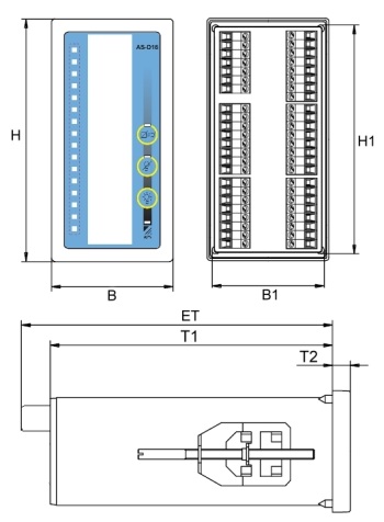
| H | B | H1 | B1 | ET | T1 | T2 |
|---|---|---|---|---|---|---|
| 144 mm | 72 mm | 136 mm | 65 mm | 75 mm | 52 mm | 8.5 mm |